顯示具有 Arduino 標籤的文章。 顯示所有文章

2016年7月1日 星期五

Arduino: SimpleTimer

since: 2016/07/01
update: 2016/07/01

reference:
1. Arduino Playground - SimpleTimer Library


A.
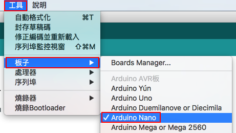
設定好 Arduino 的板子與序列埠

-----------------------------------------------------------------------------------------------

B. 匯入 SimpleTimer 程式庫:

     1. 到 Arduino Playground - SimpleTimer Library
         下載 SimpleTimer.h 與 SimpleTimer.cpp

     2. 將這二個檔案, 放到新增的 SimpleTimer 資料夾內, 並壓縮成 SimpleTimer.zip

     3. 開啟 Arduino, 將  SimpleTimer 匯入:
         > 草稿碼 > 匯入程式庫 > 加入 .ZIP 程式庫... > 選取剛剛的 SimpleTimer.zip 檔案

      > 完成後, 再檢查一次: (最底下會列出 SimpleTimer 的程式庫)

     4. 檢查實際的程式庫位置:  
         > 文件 > Arduino > libraries > SimpleTimer

-----------------------------------------------------------------------------------------------

C. Arduino 程式碼:

    1. 開啟 Arduino, 撰寫以下的程式碼:
#include <SimpleTimer.h>

// the timer object
SimpleTimer timer;

int timerId;

// a function to be executed periodically
void repeatMe() {
    Serial.print("Uptime (s): ");
    Serial.println(millis() / 1000);

    if(millis() / 1000 == 5) {
        Serial.println(">>> you got 5 second");
    }
    else if(millis() / 1000 == 10) {
        Serial.println(">>> you got 10 second");
    }
}

void setup() {
    Serial.begin(9600);
    timerId = timer.setInterval(1000, repeatMe);
    timer.disable(timerId);
   
    if(timer.isEnabled(timerId) == false) {
        Serial.println(">>> setup(): timer is not Enabled");
    }
}

void loop() {
   
    if(timer.isEnabled(timerId)) {
      timer.run();
    }
    else {
      timer.enable(timerId);

      if(timer.isEnabled(timerId)) {
          Serial.println(">>> loop(): timer is Enabled");
      }
    }
}

2016年6月15日 星期三

Unreal: Arduino Plugin For UE4

since: 2016/06/15
update: 2017/03/23

reference:
1. Plugin UE4Duino - Arduino to UE4 plugin Release!
2. UDK - UE4Duino Plugin
3. loveunrealengine | TIPS


A. 系統環境:
    OS: Windows 8
    UE: UE 4.10

-----------------------------------------------------------------------------------------------

B. Arduino
    1. 將 Arduino 連上電腦, 確認 COM port 的號碼(在此為 4)

    2. 設定好 Arduino 的板子與序列埠

    3. 以燒錄器上傳 Arduino 的程式碼:
void setup() {
  // put your setup code here, to run once:
  Serial.begin(9600);
}

void loop() {
  // put your main code here, to run repeatedly:
  Serial.println(random(1, 100));
  delay(1000); // wait for a second
}


-----------------------------------------------------------------------------------------------

C. Unreal Engine

   1. 到 Plugin UE4Duino - Arduino to UE4 plugin Release! 下載檔案:
       UE4Duino_4_10.zip
, 解壓縮後得到 UE4Duino 資料夾

   2. 新增空白的 UE 專案: UE4Duino_01, 在專案下新增 Plugins 資料夾, 並將剛剛的
       UE4Duino 資料夾放入.

   3. 開啟 UE4Duino_01 專案, 檢查 plugin:
       Edit > Plugins:

   4. 進入 UE4Duino_01 專案的 Level Blueprint, 在 Event Graph 修改如下:

   5. Complie Level Blueprint 後關閉 Level Blueprint,
      回到 Level Editor, 在 Content Browser 存檔(Save All) 後, Build -> Play

-----------------------------------------------------------------------------------------------

D. Turn the LED on /off

   1. Arduino:
int led = 13; // LED pin number
String content = "";
char character;

void setup() {
  Serial.begin(9600);
 
  // initialize digital pin 13 as an output.
  pinMode(led, OUTPUT);
 
  delay(1000);
 
  Serial.println("setup ok");
}

void loop() {
  delay(100); // delay in between reads for stability
 
  // UE4 Input
  while(Serial.available() > 0)
  {
    character = Serial.read();
    if(character != '^') {
      content.concat(character);
    }
    else {
      if (content == "ON") {
        digitalWrite(led, HIGH);   // turn the LED on (HIGH is the voltage level)
        Serial.println("turn the LED on");
      }
      else if(content == "OFF") {
        digitalWrite(led, LOW);    // turn the LED off by making the voltage LOW
        Serial.println("turn the LED off");
      }
      content = "";
     
    } // end of else
   
  } // end of while
}


   2. Unreal

   3. 結果:
       按下: o 鍵 ---> Serial Opened
                 h 鍵 ---> turn the LED on // HIGH is the voltage level
                 l 鍵 ---> turn the LED off // making the voltage LOW
                 c 鍵 ---> Serial Closed

-----------------------------------------------------------------------------------------------

E. UE4Duino 2.0

   1. Arduino:
void setup() {
 // put your setup code here, to run once:
 Serial.begin(9600);
}

void loop() {
 // put your main code here, to run repeatedly:
 //Serial.println(random(1, 100));
 //Serial.print("#");

 Serial.print(random(1, 100)); // not need use
Serial.println
 //Serial.println("#");

 delay(1000); // wait for a second
}


   2. Unreal:

2016年3月2日 星期三

Raspberry Pi: Connected Arduino Using I2C

since: 2016/02/25
update: 2016/03/03

reference:
1.Raspberry Pi and Arduino Connected Using I2C - OscarLiang.net
2. [I2C] onRequest and onReceive as slave with Raspberry Pi Master

A. 檢查 Raspberry Pi:
   
1. Linux 版本

    $ uname -a
Linux raspberrypi 4.1.17-v7+ #843 SMP Mon Feb 15 23:35:33 GMT 2016 armv7l GNU/Linux

    2. python 版本
    $ python -V
Python 2.7.9

-----------------------------------------------------------------------------------------------

B. 安裝 I2C 與 python相關套件:
    $ sudo apt-get install python-smbus
    $ sudo apt-get install python3-smbus // for python3
    $ sudo apt-get install i2c-tools

    // check
    $ sudo aptitude search smbus
p   pypy-smbus-cffi        - This Python module allows SMBus access through the I2C /dev              
i   python-smbus            - Python bindings for Linux SMBus access through i2c-dev                   
v   python2.7-smbus      -                                                                          
i   python3-smbus          - Python 3 bindings for Linux SMBus access through i2c-dev


-----------------------------------------------------------------------------------------------

C. 安裝 I2C 的 Kernel Support:
     $ sudo raspi-config
        > 9 Advanced Options

        > A7 I2C

        > Yes
       ....
        > Yes

-----------------------------------------------------------------------------------------------

D. 檢查設定(選擇性)
     $ cat /etc/modules
....
i2c-dev
    
     $ cat /etc/modprobe.d/raspi-blacklist.conf
# ...
# ...


    $ cat /boot/config.txt
....
dtparam=i2c_arm=on

    $ cat /etc/group | grep i2c
i2c:x:998:pi
      // $ sudo adduser pi i2c

-----------------------------------------------------------------------------------------------

E. I2C 測試:
    $ sudo i2cdetect -y 1
     0  1  2  3  4  5  6  7  8  9  a  b  c  d  e  f
00:          -- -- -- -- -- -- -- -- -- -- -- -- --
10: -- -- -- -- -- -- -- -- -- -- -- -- -- -- -- --
20: -- -- -- -- -- -- -- -- -- -- -- -- -- -- -- --
30: -- -- -- -- -- -- -- -- -- -- -- -- -- -- -- --
40: -- -- -- -- -- -- -- -- -- -- -- -- -- -- -- --
50: -- -- -- -- -- -- -- -- -- -- -- -- -- -- -- --
60: -- -- -- -- -- -- -- -- -- -- -- -- -- -- -- --
70: -- -- -- -- -- -- -- -- 


    $ ls /dev/i2c*
/dev/i2c-1
-----------------------------------------------------------------------------------------------

F. Arduino Code:
#include <Wire.h>

#define SLAVE_ADDRESS 0x04
int number = 0;
int state = 0;

void setup() {
    pinMode(13, OUTPUT);
    Serial.begin(9600); // start serial for output
    // initialize i2c as slave
    Wire.begin(SLAVE_ADDRESS);

    // define callbacks for i2c communication
    Wire.onReceive(receiveData);
    Wire.onRequest(sendData);
    //Serial.println(“Ready!”);
}

void loop() {
    delay(100);
}

// callback for received data
void receiveData(int byteCount){

    while(Wire.available()) {
        number = Wire.read();
        //Serial.print(“data received: “);
        //Serial.println(number);


        if (number == 1){

            if (state == 0){
                digitalWrite(13, HIGH); // set the LED on
                state = 1;
            }
            else{
                digitalWrite(13, LOW); // set the LED off
                state = 0;
            }
        }
    }
}

// callback for sending data
void sendData(){
    Wire.write(number);
}


-----------------------------------------------------------------------------------------------

G. Raspberry Pi's  Python Code:
#!/usr/bin/python
#encoding: utf-8

import smbus
import time

# for RPI version 1, use "bus = smbus.SMBus(0)"
bus = smbus.SMBus(1)

# This is the address we setup in the Arduino Program
address = 0x04

def writeNumber(value):
    bus.write_byte(address, value)
    # bus.write_byte_data(address, 0, value)
    return -1

def readNumber():
    number = bus.read_byte(address)
    # number = bus.read_byte_data(address, 1)
    return number

while True:
    var = input("Enter 1 – 9:")
    if not var:
        continue

    writeNumber(var)
    print "RPI: Hi Arduino, I sent you ", var
    # sleep one second
    time.sleep(1)

    number = readNumber()
    print "Arduino: Hey RPI, I received a digit ", number
    print


-----------------------------------------------------------------------------------------------

H. 備註:
When we use read_i2c_block_data(), It was too fast to write a command byte and read the data.

In that time, if we use Serial.println() to print log to serial. Arduino will can not follow the speed. and it missing the i2c read flag.

So, the dataReceive() funtion will not be run at all.

The solution is simple: just do not use Serial library until the i2c is free.

2015年10月30日 星期五

Processing: Get Datas From Adafruit BNO055 Sensor

since: 2015/10/30
update: 2015/11/01

reference:
1. Adafruit BNO055 Absolute Orientation Sensor

A. 硬體:

    1. Adafruit BNO055 Sensor
    2. Arduino Nano
    3. Mac OS X

-----------------------------------------------------------------------------------------------

B. 軟體:
    1. Arduino IDE
    2. Processing

-----------------------------------------------------------------------------------------------

C. 將 Arduino 程式碼寫入:

     1. 下載 Adafruit_BNO055 driver 與 Adafruit_Sensor
 
     2. 解壓縮後, 將其資料夾更名為: Adafruit_BNO055 與 Adafruit_Sensor

     3. 複製到 /Users/Lanli/Documents/Arduino/libraries 下:

     4. 打開  Arduino IDE , 參考剛剛 libraries 資料夾下的
         /Adafruit_BNO055/examples/rawdata/rawdata.ino, 撰寫以下的程式碼:
 
#include <Wire.h>
#include <Adafruit_Sensor.h>
#include <Adafruit_BNO055.h>
#include <utility/imumaths.h>

/* This driver reads raw data from the BNO055

   Connections
   ===========
   Connect SCL to analog 5
   Connect SDA to analog 4
   Connect VDD to 3.3V DC
   Connect GROUND to common ground

   History
   =======
   2015/MAR/03  - First release (KTOWN)
*/

/* Set the delay between fresh samples */
#define BNO055_SAMPLERATE_DELAY_MS (100)

Adafruit_BNO055 bno = Adafruit_BNO055();

/**************************************************************************/
/*
    Arduino setup function (automatically called at startup)
*/
/**************************************************************************/

void setup(void)
{
  Serial.begin(9600);
  Serial.println("Orientation Sensor Raw Data Test"); Serial.println("");

  /* Initialise the sensor */
  if(!bno.begin())
  {
    /* There was a problem detecting the BNO055 ... check your connections */
    Serial.print("Ooops, no BNO055 detected ... Check your wiring or I2C ADDR!");
    while(1);
  }

  delay(1000);

  /* Display the current temperature */
  /*
  int8_t temp = bno.getTemp();
  Serial.print("Current Temperature: ");
  Serial.print(temp);
  Serial.println(" C");
  Serial.println("");
  */

  bno.setExtCrystalUse(true);

  Serial.println("Calibration status values: 0=uncalibrated, 3=fully calibrated");
}

/**************************************************************************/
/*
    Arduino loop function, called once 'setup' is complete (your own code
    should go here)
*/
/**************************************************************************/

void loop(void)
{
  // Possible vector values can be:
  // - VECTOR_ACCELEROMETER - m/s^2
  // - VECTOR_MAGNETOMETER  - uT
  // - VECTOR_GYROSCOPE     - rad/s
  // - VECTOR_EULER         - degrees
  // - VECTOR_LINEARACCEL   - m/s^2
  // - VECTOR_GRAVITY       - m/s^2

 
  // EULER
  imu::Vector<3> euler = bno.getVector(Adafruit_BNO055::VECTOR_EULER);

  /* Display the floating point data */
  /*
  Serial.print("X: ");
  Serial.print(euler.x());
  Serial.print(" Y: ");
  Serial.print(euler.y());
  Serial.print(" Z: ");
  Serial.print(euler.z());
  Serial.print("\t\t");
  */

  Serial.print("euler: ");
  Serial.print(euler.x());
  Serial.print(" ");
  Serial.print(euler.y());
  Serial.print(" ");
  Serial.print(euler.z());
  Serial.print(" "); 
 
  // GYROSCOPE
  imu::Vector<3> gyroscope = bno.getVector(Adafruit_BNO055::VECTOR_GYROSCOPE);

  Serial.print("gyro: ");
  Serial.print(gyroscope.x());
  Serial.print(" ");
  Serial.print(gyroscope.y());
  Serial.print(" ");
  Serial.print(gyroscope.z());
  Serial.print(" ");
 
  // ACCELEROMETER
  imu::Vector<3> accelerometer = bno.getVector(Adafruit_BNO055::VECTOR_ACCELEROMETER);

  Serial.print("acc: ");
  Serial.print(accelerometer.x());
  Serial.print(" ");
  Serial.print(accelerometer.y());
  Serial.print(" ");
  Serial.print(accelerometer.z());
  Serial.print(" "); 
 
  /*
  // Quaternion data
  imu::Quaternion quat = bno.getQuat();
  Serial.print("qW: ");
  Serial.print(quat.w(), 4);
  Serial.print(" qX: ");
  Serial.print(quat.y(), 4);
  Serial.print(" qY: ");
  Serial.print(quat.x(), 4);
  Serial.print(" qZ: ");
  Serial.print(quat.z(), 4);
  Serial.print("\t\t");
  */


  /* Display calibration status for each sensor. */
  uint8_t system, gyro, accel, mag = 0;
  bno.getCalibration(&system, &gyro, &accel, &mag);
  //Serial.print("CALIBRATION: Sys=");
  Serial.print("CAL: Sys=");
  Serial.print(system, DEC);
  Serial.print(" Gyro=");
  Serial.print(gyro, DEC);
  Serial.print(" Accel=");
  Serial.print(accel, DEC);
  Serial.print(" Mag=");
  Serial.println(mag, DEC);

  delay(BNO055_SAMPLERATE_DELAY_MS);
}

     4. 選取板子:
         Arduino > 工具 > 板子 > Arduino Nano 

     5. 選取序列埠:
         Arduino > 工具 > 序列埠 > /dev/cu.usbserial-AJ02WWCS 


     6. 上傳:
         Arduino > 檔案 > 上傳  

     7. 完成:

-----------------------------------------------------------------------------------------------

D. Processing:
    1. 相關程式碼如下:

void setup() {
....
  // initial Serial
  println(Serial.list());

  Serial port;
  // baudRate: 從一裝置發到另一裝置的位元率,即每秒鐘多少位元(bit/s)。
  int arduinoBaudRate = 9600;     
  int arduinoPortIndex;
  int lineFeed= 10;         // ASCII: line feed (new line)
  String arduinoSerialName = "
usbserial";
  String arduinoPort;

  // automatic set arduino port index 

 
for (int i = 0; i < Serial.list ().length; i++) {
    if (Serial.list()[i].indexOf(
arduinoSerialName) > 0) { // if find string "usbserial"
      arduinoPortIndex = i;
      println(">>> arduino Port Index = " + arduinoPortIndex)      
      break;
    }
  }

    arduinoPort = Serial.list()[arduinoPortIndex];
    port = new Serial(this, arduinoPort, arduinoBaudRate);
    port.bufferUntil(lineFeed);

....
}

void serialEvent(Serial p) { 
  String rawStr = p.readString();
  println(">>> BNO055 = " +  rawStr);
}


    2. 執行結果:

2015年10月20日 星期二

openFrameworks: Serial Read String From Arduino Simulated Sensor

since: 2015/10/20
update: 2015/10/22
reference:
1. Serial read string from Arduino - 【oF】openFrameworks

A. Arduino 程式: 
// arduino_sensor.ino
long randNumber;
float randFloat;

String xAxis = "X: ";
String yAxis = "Y: ";
String zAxis = "Z: ";

String xValue = "";
String yValue = "";
String zValue = "";

void setup(){
  Serial.begin(9600);

  // if analog input pin 0 is unconnected, random analog
  // noise will cause the call to randomSeed() to generate
  // different seed numbers each time the sketch runs.
  // randomSeed() will then shuffle the random function.

  randomSeed(analogRead(0));
}

void loop() {

  // ex: X: 359.81252 Y: 11.81252 Z: 56.00005
  randNumber = random(0, 36000000);
  randFloat = randNumber / 100000.0; //
produce float random value: 0 ~ 360
  xValue = String(randFloat, 5);
 
  randNumber = random(-3600000, 3600000);
  randFloat = randNumber / 100000.0; //
produce float random value: -36 ~ 36
  yValue = String(randFloat, 5); 
 
  randNumber = random(0, 18000000);
  randFloat = randNumber / 100000.0;  //
produce float random value: 0 ~ 180
  zValue = String(randFloat, 5); 

  Serial.println(xAxis + xValue + " " + yAxis + yValue + " " + zAxis + zValue);
  delay(50);
}


-----------------------------------------------------------------------------------------------

B. openFrameworks 程式:
    1. main.cpp
#include "ofMain.h"
#include "ofApp.h"

//========================================================================
int main( ){
    ofSetupOpenGL(1024,768,OF_WINDOW);            // <-------- setup the GL context

    // this kicks off the running of my app
    // can be OF_WINDOW or OF_FULLSCREEN
    // pass in width and height too:

    ofRunApp(new ofApp());
}

-----------------------------------------------------------------------------------------------

    2. ofApp.h
#pragma once

#include "ofMain.h"

class ofApp : public ofBaseApp{

    public:
        void setup();
        void update();
        void draw();

        void keyPressed(int key);
        void keyReleased(int key);
        void mouseMoved(int x, int y );
        void mouseDragged(int x, int y, int button);
        void mousePressed(int x, int y, int button);
        void mouseReleased(int x, int y, int button);
        void windowResized(int w, int h);
        void dragEvent(ofDragInfo dragInfo);
        void gotMessage(ofMessage msg);
   
        //@add 2015/10/20 ########################################
        string ofxGetSerialString(ofSerial &serial, char until);
        string ofxTrimStringRight(string str);
        string ofxTrimStringLeft(string str);
        string ofxTrimString(string str);
   
        ofTrueTypeFont  font;
        float           readTime;           // when did we last read?
        ofSerial        serial;
        string          serialString;
};


-----------------------------------------------------------------------------------------------

    3. ofApp.cpp
#include "ofApp.h"

//--------------------------------------------------------------

//@add 2015/10/20 ########################################
string ofApp::ofxGetSerialString(ofSerial &serial, char until) {
    static string str;
    stringstream ss;
    char ch;
    int ttl=1000;
    while ((ch=serial.readByte())>0 && ttl-->0 && ch!=until) {
        ss << ch;
    }
    str+=ss.str();
    if (ch==until) {
        string tmp=str;
        str="";
        return ofxTrimString(tmp);
    } else {
        return "";
    }
}


//@add 2015/10/20 ########################################
// trim right trailing spaces

string ofApp::ofxTrimStringRight(string str) {
    size_t endpos = str.find_last_not_of(" \t\r\n");
    return (string::npos != endpos) ? str.substr( 0, endpos+1) : str;
}


//@add 2015/10/20 ########################################
// trim left trailing spaces

string ofApp::ofxTrimStringLeft(string str) {
    size_t startpos = str.find_first_not_of(" \t\r\n");
    return (string::npos != startpos) ? str.substr(startpos) : str;
}


//@add 2015/10/20 ########################################
// trim trailing spaces

string ofApp::ofxTrimString(string str) {
    return ofxTrimStringLeft(ofxTrimStringRight(str));;
}


void ofApp::setup(){
    //@add 2015/10/20 ########################################
    ofSetVerticalSync(true);
   
    ofBackground(255);
    // http://openframeworks.cc/documentation/utils/ofLog.html
    ofSetLogLevel(OF_LOG_VERBOSE);
   
    ofSetColor(0);
    font.loadFont("DIN.otf", 32);
   
    serial.listDevices();
    /*
     [notice ] ofSerial: [0] = tty.usbmodem1441
     [notice ] ofSerial: [1] = cu.usbmodem1441
     [notice ] ofSerial: [2] = tty.Bluetooth-Incoming-Port
     [notice ] ofSerial: [3] = cu.Bluetooth-Incoming-Port
     */
   
    /*
    vector<ofSerialDeviceInfo> deviceList = serial.getDeviceList();
    vector<ofSerialDeviceInfo>::iterator it = deviceList.begin();
   
    while( it != deviceList.end() ){
        ofLogVerbose() << (*it).getDeviceID() << ": " << (*it).getDeviceName();
        ++it;
    }
    */

   
    int baud = 9600;
    // Tells the computer which port to be listening to
    serial.setup(0, baud); //open the first device
   
    readTime = 0;
    serialString = "";
}

//--------------------------------------------------------------
void ofApp::update(){
    //@add 2015/10/20 ########################################
    serialString = "";
    serialString = ofxGetSerialString(serial,'\n'); //read until end of line
    if (serialString.length() > 0) {
        readTime = ofGetElapsedTimef();
        ofLogVerbose() << "serialString = " << serialString << "\n";
    }
}

//--------------------------------------------------------------
void ofApp::draw(){
    string msg;
    msg += "read: " + serialString + "\n";
    msg += "(at time " + ofToString(readTime, 3) + ")";
    font.drawString(msg, 50, 100);
}

//--------------------------------------------------------------
void ofApp::keyPressed(int key){
}

//--------------------------------------------------------------
void ofApp::keyReleased(int key){
}

//--------------------------------------------------------------
void ofApp::mouseMoved(int x, int y ){
}

//--------------------------------------------------------------
void ofApp::mouseDragged(int x, int y, int button){
}

//--------------------------------------------------------------

void ofApp::mousePressed(int x, int y, int button){
}

//--------------------------------------------------------------
void ofApp::mouseReleased(int x, int y, int button){
}

//--------------------------------------------------------------
void ofApp::windowResized(int w, int h){
}

//--------------------------------------------------------------
void ofApp::gotMessage(ofMessage msg){
}

//--------------------------------------------------------------
void ofApp::dragEvent(ofDragInfo dragInfo){
}


       備註:
       記得將 .... /openFrameworks/of_v0.8.4_osx_release/examples/ communication/
       serialExample/bin/data
內的 DIN.otf copy 到相對的位置內.


-----------------------------------------------------------------------------------------------

C. 執行結果:

2015年4月18日 星期六

Processing: Read Serial Data From Arduino

since: 2015/04/18
update: 2015/04/18
reference:
1. Connecting Arduino to Processing

A. 說明:
     目前剛開始接觸 Arduino, 藉由工作夥伴在 Arduino 上作了簡易的功能,
     先測試在 Processing 上的溝通方式.

-----------------------------------------------------------------------------------------------

B. 實作:

    1. 將 Arduino 用 USB 連結線, 連到 Mac 上.  

    2. 開啟 Processing, 新增 Sketch 專案: arduino_hello

    3. 在 arduino_hello Sketch 專案編輯區, 寫入以下程式碼:
import processing.serial.*;
Serial port;
float val;

void setup() {
  size(440, 220);
  //println(Serial.list());
  String arduinoPort = Serial.list()[2]; // 見說明
  port = new Serial(this, arduinoPort, 9600); // 9600 須先在
Arduino 上定義好  
}

void draw() {
  if(port.available()>0) {
    val = port.read();
  }
  println("val = " + val);
}


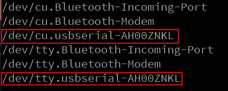
說明: 如果先執行註解的那行: println(Serial.list());  可以看到類似以下的輸出:
        其中: 第 2 與第 5 行(從第 0 行開始計算), 紅色線條匡起來的, 就是 Arduino
                  連到 Mac 上的 Serial Port. (二者皆可使用)  

-----------------------------------------------------------------------------------------------

C. 執行結果: