2012年5月14日 星期一

OpenGL: Nate Robins - Tutors 02

since: 2012/05/14
update: 2012/05/14

reference:
1. Nate Robins - OpenGL - Tutors
2. CG OpenGL 3D viewing-course 7
3. Computer Graphics 2011 (Chap 5:Viewing Transformation)
4. 靜宜大學資工系電腦圖學課程網頁 (OpenGL5.ppt)
5. Jaly's Web: 研究資料 (投影的介紹)
6. CS 330 Graphics--Viewing

Projection(投影)

A. 概觀
      1. 概觀圖


      2. 說明
            頂點轉換過程的其中
三個階段:
            a. 階段一:
                藉由 Model-View Matrix 轉換到 Camera
(Eye) Coordinates
                (1). 將 matrix mode 切換到 GL_MODELVIEW, 並呼叫 glLoadIdentity()
                       (單位矩陣).

                (2). 呼叫 gluLookAt().

                (3). model 轉換: 位移, 旋轉, 縮放 ....

            b. 階段二:
                藉由 Projection Matrix 轉換到 Homogeneous(Clip) Coordinates
                (1). 將 matrix mode 切換到 GL_PROJECTION, 並呼叫 glLoadIdentity()
                       (單位矩陣).


                (2). 如果要採用透視投影, 就呼叫 gluPerspective().

                (3).
如果要採用正交投影, 就呼叫 gluOrtho2D().


            c. 階段三:
                藉由 Viewport Transformation 轉換到 Window Coordinates

                呼叫 glViewport().

     3. 備註:       
          Perspective division
          這一個階段把 clip coordinate 的齊次座標 (x, y, z, w) 轉成三維座標
          (x/w, y/w, z/w)
, 稱之為 normalized device coordinates(正規化裝置座標).


-------------------------------------------------------------------------------------------


B. 階段一的 gluLookAt()
     1. 說明:
         Model-View 矩陣是用來置放 camera 的位置, 通常可藉由 gluLookAt() 函式
         來輕易達成.

     2. gluLookAt() 函式說明:
         gluLookAt(eyex, eyey, eyez, atx,  aty,  atz, upx,  upy,  upz);

          a. (eyex, eyey, eyez): 代表眼睛(或相機)的擺放位置(座標).

          b. (atx,  aty,  atz): 代表眼睛(或相機)所觀看的位置(座標).

          c. (upx,  upy,  upz): 代表眼睛(或相機)上方的向量.
              備註: 亦即眼睛(或相機)的正上方是哪個方向?
              例如:
              (upx, upy, upz) = (0, 1, 0) // 相機的正上方朝向 Y 軸.

              (upx, upy, upz) = (2, 1, 0) // 相機的正上方朝向 (2, 1, 0) 方向.

-------------------------------------------------------------------------------------------

C. 階段二的正交投影
     1. 圖示:
     說明:
         a. 正交投影的可視空間是平行六面體.

         b. 近端截取平面(near plane)與遠端截取平面(far plane)是一樣大的.

         c. 物體與觀察點距離的遠近並不會影響其顯示的大小

     2. 函式:
         glOrtho(GLdouble leftX, GLdouble rightX,
                        GLdouble bottomY, GLdouble topY,
                        GLdouble nearZ, GLdouble farZ);

         // 與 glOrtho() 相同, 其中 nearZ = 1 且 farZ = 1.
         glOrtho2D(GLdouble leftX, GLdouble rightX,
                              GLdouble bottomY, GLdouble topY);

-------------------------------------------------------------------------------------------

D. 階段二的透視投影
     1. 圖示:

     說明:
         a. 近端截取平面(near plane)與遠端截取平面(far plane)並不一樣大.
         b. 物體會隨著與觀察點的距離而改變大小

     2. 函式:
          glFrustum( GLdouble leftX, GLdouble rightX,
                                GLdouble bottomY, GLdouble topY,
                                GLdouble nearZ, GLdouble farZ);

   
    // 建議使用
    gluPerspective(GLdouble fovy, GLdouble aspect, GLdouble near, GLdouble far);
     說明:
       a. fovy: field of view Y; 上下二個平面的角度.
       b. aspect: 寬與高的比例(width/height).

-------------------------------------------------------------------------------------------

E. 階段三的 glViewport()
      1. 說明:
          a. viewport 是指視窗上的一塊矩形區域. 可透過 viewport transformation
              將 normalized device coordinates 轉換成視窗座標.

          b. 藉由設定 viewpot 的原點位置, 寬度, 和高度. 調整寬和高之間的比例
              可以產生放大, 縮小, 壓扁, 拉長的效果.

      2. 函式:
           glViewport(GLint x, GLint y, GLsizei width, GLsizei height);

-------------------------------------------------------------------------------------------

F. The Projection Tutorial Program
    1. 開啓 I touchs: OpenGL: Nate Robins - Tutors 00 中調整好的專案, 將
         active scheme 選為 projection 後執行.


    2. gluLookAt() // 置放 camera 的位置
        a. 相機位置往正 X 軸方向移動 2 個單位.

        b. 相機所觀看的中心位置, 往負 Y 軸方向移動 1 個單位.

        c. 原本相機的正上方朝向 Y 軸(0.0, 1.0, 0.0);
           調整成
相機正上方的方向向量為: (1.0, 1.0, 0.0). 

    3. gluPerspective() // 透視投影
          a. 擴大投影的視野角度(field of view Y), 如同廣角鏡的效果.

          b. 調整投影的 寬 / 高 之比例. (代表: 水平方向的視野)

          c. 當投影的 near plane 距離設的太遠, 例如, 在物體模型的後方,
              可能只會看到模型背部的部分切面.

          d. 同樣地, 當投影的 far plane 距離設的太近, 例如, 與物體模型相交會,
              可能只會看到模型前半部切面.

2012年5月10日 星期四

OpenGL: Nate Robins - Tutors 01

since: 2012/05/09
update: 2012/05/10

reference:
1. Nate Robins - OpenGL - Tutors
2. Tutorial 3 : Matrices | opengl-tutorial.org
3. 齊次座標

Transformation(轉換)

A. Homogeneous coordinates(齊次座標): 

      1. 齊次座標可以讓我們使用同一種數學方程式, 來對點(頂點)或向量處理:
          平移
, 縮放與旋轉的問題.

      2. 在齊次座標中, 我們引入了 w 參數到原本三維的座標: (x, y ,z) 裡:
           (x, y, z, w), w 代表座標軸的遠近參數. 要將齊次座標轉換為三維座標,
           其方式為: (x/w,  y/w, z/w).

      3. (x, y, z, w) 在齊次座標中:
          當 w == 1, 代表此為空間中的一個位置(點或頂點). => (x/1, y/1, z/1) = (x, y, z)
          當 w == 0, 代表此為一個向量. => (x/0, y/0, z/0)

-------------------------------------------------------------------------------------

B. Transformation Matrices(轉換矩陣):
     1. 矩陣介紹:
          a. 簡單來說, 矩陣是一個在預先定義好列(row, 水平向)與欄(column, 垂直向)
              的架構裡存放數值的陣列. 舉例: 2(row) x 3(column) 矩陣如下所示:

          b. 在 3D 繪圖中, 我們會使用 4x4 矩陣. 藉由將矩陣與頂點相乘, 可以用來
              轉換 (x,y,z,w) 頂點:    

             (4x4)矩陣 x 頂點 = 轉換的頂點 (x', y', z', w')

****************************************************************

     2. Identity Matrix(單位矩陣):
          a. 說明: 在線性代數中, n 階單位矩陣, 是一個 n x n 的方形矩陣, 其主對角線元素
                         為 1, 其餘元素為 0.

          b. 單位矩陣乘以任何座標(x, y, z, w), 其結果還是原始座標(x, y, z, w).


****************************************************************

    3. Translation Matrices(位移矩陣):
           a. 位移矩陣如下所示, 其中 X, Y, Z 分別為各軸的位移量.

           b. 例如: 將頂點 (10,10,10,1) 往 X 軸方向位移 10 個單位, 結果為: (20,10,10,1)
               (備註: 在此 w = 1, 所以是頂點)

           c. 接著, 來看看一個朝著負 Y 軸方向的向量 (0, 0, -1, 0), 往 X 軸方向位移 10 個
               單位, 其結果會是如何? (備註: 在此 w = 0, 所以是向量)
               結果: 原始向量不會改變.

****************************************************************


    4. Scaling Matrices(縮放矩陣):
          a. 縮放矩陣如下所示, 其中 X, Y, Z 分別為各軸的縮放比例.

          b. 例如, 對一個座標(x, y, z, w)在各方向放大 2 個單位:

          c. 備註:
               (1). w 值不會變.
               (2). 單位矩陣為縮放矩陣的特例, 當其縮放比例: (X,Y,Z) = (1,1,1).
               (3). 單位矩陣亦為位移矩陣的特例, 當其各軸位移量: (X,Y,Z) = (0,0,0).

****************************************************************

     5. Rotation Matrices(旋轉矩陣):
      (圖片來源: 齊次座標)

****************************************************************

     6. Culumating Transformations(轉換計算):
          a. 例如: 轉換的座標 = 縮放矩陣 x 旋轉矩陣 x 位移矩陣 x 原始座標
              說明: 實際上矩陣相乘的順序為: 位移(先), 旋轉, 縮放(最後). 
                        (從右到左, 離遠始座標最近的先計算)

          b. 事實上, 以上的順序也是遊戲角色與其它物品常會使用到的:
              先置放位置(位移), 然後改變方向(旋轉), 接著縮放大小(如果有需要的話).

-------------------------------------------------------------------------------------

C. The Model, View and Projection Matrices
      1. 說明:
         Model, View 與 Projection(投影) 矩陣, 是一個可以用來清楚的區分轉換的方便工具.

****************************************************************

      2. The Model Matrix:
          a. Model Space:
              所有的頂點是相對於此 model 的中心點而定義的, 亦即物件的中心點是 (0,0,0).

          b. World Space:
              所有的頂點是相對於世界的中心而定義的.

            c. 藉由 Model Matrix, 我們將一個 Model 從 Model Space 移到了 World Space.

****************************************************************

      3. The View Matrix:
           a. Camera Space:
               所有的頂點是相對於 camera 而定義的.


           b. 最初 camera 是在 World Space 的原點(0,0,0), 我們可藉由移動 camera 來
               相對的移動整個世界(從 camera 的觀點來看). 

           c. 所以, 將 camera 向右 (正 X 軸) 移動 3 個單位, 等同於將整個世界(包含世界
               座標裡的 Model)向左 (負 X 軸) 移動 3 個單位. 

           d. 藉由 View Matrix, 我們將一個 Model 從 World Space 移到了 Camera Space.


****************************************************************

      4. The Projection Matrix:
            a. Homogeneous Space:
                所有被定義在一個小立方體(cube)裡的頂點, 才會在螢幕上呈現.

            b. 在 Camera Space 中, 座標為 (0, 0) 的點將會被畫在螢幕的中心. 

            c. Perspective Projection(透視投影):
                我們不能只用 (x, y) 座標來決定物件擺放在螢幕的位置, 也要將物件到 camera
                的距離(z)計算在內. 對於二個有相似 x, y 座標的頂點, 其中有較大 z 座標的頂點
                (代表距離 camera 較近), 將會比另一個頂點更位在螢幕的中心處. 這就叫做
                透視投影
.

            d. 最後, 藉由 Projection Matrix, 我們將一個 Model 從 Camera Space 移到了
                 Homogeneous
Space.

-------------------------------------------------------------------------------------

D. The Transformation Tutorial Program
     1. 開啓 I touchs: OpenGL: Nate Robins - Tutors 00 中調整好的專案, 將
         active scheme 選為 transformation 後執行.


****************************************************************
     2. Translation(位移):

        glTranslatef(X 軸位移量, Y 軸位移量, Z 軸位移量);
       說明: 此處車子向正 X 軸位移 0.2 個單位;
                 相對的, camera 會向負 X 軸位移 0.2 個單位.

****************************************************************
     3. Rotation(旋轉):

        glRotatef(旋轉角度, X 軸向量, Y 軸向量, Z 軸向量);

****************************************************************
     4. Scaling(縮放):

        glScalef(沿 X 軸的縮放係數, 沿 Y 軸的縮放係數, 沿 Z 軸的縮放係數);
       說明: 此處沿 Z 軸放大 1.50 倍, 就像車子沿著正前方開過來.

2012年5月9日 星期三

OpenGL: Nate Robins - Tutors 00

since: 2012/05/09
update: 2012/05/09

reference:
1. Nate Robins - OpenGL - Tutors
2. Linux 基本指令

教學程式的專案調整


A. 說明:
     接下來的文章, 主要會對: Nate Robins - OpenGL - Tutors 教學程式本身的執行結果,
     作部分相關的說明, 以期在開始寫程式前, 能對繪圖觀念有更多的瞭解.

-------------------------------------------------------------------------------------------------

B. 下載原始檔案並編譯執行:
     1. 在教學程式網站中, 下載: Tutors source code package (tutors-src.zip 920KB) .

     2. 下載後, 解壓縮到自定的專案目錄位置(在此為: /Lanli/RD/Projects/OpenGL),
          進入 tutors 目錄後, 點二下 tutors.xcodeproj 開啓此教學專案. 

     3. 直接執行專案, 會出現以下的錯誤訊息:
         說明:
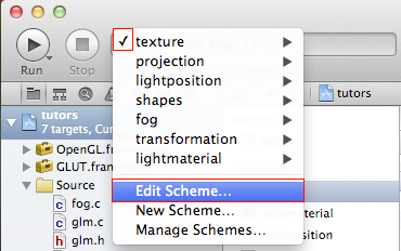
         a. 在此專案裡, 預設執行的 active scheme (左上方) 為: texture
         b. 錯誤訊息為: data/fishermen.ppm: No such file or directory

-------------------------------------------------------------------------------------------------

C. 調整專案:

     1. 根據之前的錯誤訊息, 稍微看一下 texture.c 檔案:
....
int main(int argc, char** argv)
{
    image = glmReadPPM("data/fishermen.ppm", &iwidth, &iheight);
    if (!image)
        exit(0);
....
    return 0;
}

    說明: 在讀取 .ppm 檔案時, 其讀取的相對位置是在 data 目錄下.

     2. 但是剛剛我們解壓縮檔案後, 在 tutors 專案目錄下有一個 data 目錄,
         並且在 data 目錄內也有許多的模型檔案, 看起來並沒有錯啊.

     3. 原因是: 當 Xcode 的程式實際在執行時, 預設會去讀取的文件目錄是在:
         ~/Library/Developer/Xcode/DerivedData 目錄下的相對專案名稱目錄.
         $ cd ~/Library/Developer/Xcode/DerivedData
         $ ls -rtl // 列出所有檔案的詳細資料(最久排至最近)
....
drwxr-xr-x@ 6 lanli  staff  204  4 24 15:56 tutors-fxcrcvuschgpjhahdvxmcxojrmxs
drwxr-xr-x@ 6 lanli  staff  204  5  5 09:41 hello-fvorgiypjrbadhequkcvfjqbenmd
drwxr-xr-x@ 6 lanli  staff  204  5  8 11:11 bunnyTest-eptjovdmltxrjjasgeinzgzhjfow
drwxr-xr-x@ 4 lanli  staff  136  5  8 14:32 teapot-ciclmzkmulwutdcgkxofkguajbdw    

     4. 解決方式:
          a. 說明: 必須針對每個 active scheme 來設定, 以下以 texture 為例.

          b. 在選取 texture scheme 的情況下, 點選 "Edit Scheme".

          c. 確認上方的 Scheme(可切換) 為 texture
             > 左方選取 "Run texture Debug"
             > 選擇右邊的 Options Tab
             > 於下方的 Working Directory 勾選: Use Custom working directory:
             > 選取目錄位置(在此為: /Lanli/RD/Projects/OpenGL/tutors)
             > OK

          d. 按照同樣的方式, 分別對以下其它的 scheme 作相同的調整:
               projection, lightposition, shapes, fog, transformation 與 lightmaterial.

              備註: 其實可以在 "Edit Scheme" 時, 切換上方的 Scheme
                         來分別設定好後(copy目錄位置), 再按下 OK.

-------------------------------------------------------------------------------------------------

D. 編譯與執行:
      選取 texture scheme, 編譯執行結果如下:

2012年5月1日 星期二

OpenGL: 基本幾何圖形之二

since: 2012/05/01
update: 2012/05/01

reference:
OpenGL: A Primer, 3/e

基本幾何圖形之二: 線


A. 說明:
      延續之前文章: I touchs: OpenGL: 基本幾何圖形之一 的專案.

-----------------------------------------------------------------------

B. 畫線前置處理: 
      1. 開啓 draw.h 檔案, 修改如下:
....
//@add: drawing
void drawPoints(); // 畫點
void drawLines(); // 畫線

      2. 開啓 draw.cpp 檔案, 修改如下:
....
// 畫線
void drawLines()
{
    // Clear the buffer
    glClear(GL_COLOR_BUFFER_BIT);

    // Let us begin drawing
   

    // Ok we are done drawing
   

    // Write this out to the screen
    glFlush();
}

      3. 開啓 main.cpp 檔案, 修改如下:
....
int main(int argc, char * argv[])
{
...
    // Set the callback function, will be called as needed
    //glutDisplayFunc(drawPoints); // 畫點
    glutDisplayFunc(drawLines); // 畫線
....
}
....

-----------------------------------------------------------------------

C. 畫線段(Lines)
     1. 開啓 draw.cpp 檔案, 修改如下:
....
// 畫線
void drawLines()
{
    // Clear the buffer
    glClear(GL_COLOR_BUFFER_BIT);

    //@add: attributes for line
    glLineWidth(5.0); // default: 1.0  

    // Let us begin drawing
    glBegin(GL_LINES);

    // Specify the points
    glColor3f(1.0, 1.0, 1.0); // Set the color state: white
    glVertex2f(-0.5, -0.5);
   
    glColor3f(1.0, 0.0, 0.0); // Set the color state: red
    glVertex2f(-0.5, 0.5);
   
    glColor3f(0.0, 1.0, 0.0); // Set the color state: green
    glVertex2f(0.5, 0.5);
   
    glColor3f(0.0, 0.0, 1.0); // Set the color state: blue
    glVertex2f(0.5, -0.5);

    // Ok we are done drawing
    glEnd();

    // Write this out to the screen
    glFlush();
}

     2. 編譯並執行:

-----------------------------------------------------------------------

D. 畫線條(Line Strip)

      1. 開啓 draw.cpp 檔案, 修改如下:
....
void drawLines()
{
    // Clear the buffer
    glClear(GL_COLOR_BUFFER_BIT);
   
    //@add: attributes for line
    glLineWidth(5.0); // default: 1.0   

    // Let us begin drawing
    //glBegin(GL_LINES);
    glBegin(GL_LINE_STRIP);

    // Specify the points
    glColor3f(1.0, 1.0, 1.0); // Set the color state: white
    glVertex2f(-0.5, -0.5);
   
    glColor3f(1.0, 0.0, 0.0); // Set the color state: red
    glVertex2f(-0.5, 0.5);
   
    glColor3f(0.0, 1.0, 0.0); // Set the color state: green
    glVertex2f(0.5, 0.5);
   
    glColor3f(0.0, 0.0, 1.0); // Set the color state: blue
    glVertex2f(0.5, -0.5);
   
    // Ok we are done drawing
    glEnd();
   
    // Write this out to the screen
    glFlush();
}

      2. 編譯並執行:

-----------------------------------------------------------------------

E. 畫線圈(Line Loop)
      1. 開啓 draw.cpp 檔案, 修改如下:
....
void drawLines()
{
    // Clear the buffer
    glClear(GL_COLOR_BUFFER_BIT);
   
    //@add: attributes for line
    glLineWidth(5.0); // default: 1.0   

    // Let us begin drawing
    //glBegin(GL_LINES);
    //glBegin(GL_LINE_STRIP);
    glBegin(GL_LINE_LOOP);

    // Specify the points
    glColor3f(1.0, 1.0, 1.0); // Set the color state: white
    glVertex2f(-0.5, -0.5);
   
    glColor3f(1.0, 0.0, 0.0); // Set the color state: red
    glVertex2f(-0.5, 0.5);
   
    glColor3f(0.0, 1.0, 0.0); // Set the color state: green
    glVertex2f(0.5, 0.5);
   
    glColor3f(0.0, 0.0, 1.0); // Set the color state: blue
    glVertex2f(0.5, -0.5);
   
    // Ok we are done drawing
    glEnd();
   
    // Write this out to the screen
    glFlush();
}

      2. 編譯並執行:

-----------------------------------------------------------------------

F. 點畫(Stipple)
      1. 設定直線目前點畫模式:
          void glLineStipple(GLint factor, GLshort pattern);


          a. pattern 參數: 由 1 或 0 組成的 16-bit 值, 從低位元開始算起, 來對特定直線
                                       的每一個像素進行點畫處理. 如果位元值為 1 就畫出此像素,
                                       否則就不會畫.

          b. factor 參數: 代表重複因子. 如果 pattern 中出現了 3 個 1, 並且 factor 為 2,
                                    那麼就會擴展成 6 個連續的 1. 

          c. 例如: glLineStipple(1, Ox3F07);
              pattern 為: Ox3F07, 其二進制形式為: 0011111100000111, 所以它所畫出的
              直線為: (從低位元開始) 先連續畫 3 個像素, 然後連續 5 個像素留空, 再連續
              畫 6 個像素, 最後 2 個像素留空. 如果 factor 是 2, 那麼這個模式將被擴展為:
              先連續畫 6 個像素, 然後連續 10 個像素留空, 再連續畫 12 個像素, 最後 4 個
              像素留空.

          d. 如果沒有啟用點畫功能, OpenGL 會把 pattern 當作 OxFFFF, factor 當成 1.


      2. 開啓 draw.cpp 檔案, 修改如下:
....
void drawLines()
{
    // Clear the buffer
    glClear(GL_COLOR_BUFFER_BIT);
   
    //@add: attributes for line
    glLineWidth(5.0); // default: 1.0   
   
    //@add: enable features
    glEnable(GL_LINE_STIPPLE);
   
    //glLineStipple(1, 0xffff); // default
    //glLineStipple(1, 0x3F07);
    glLineStipple(3, 0xcccc);

    // Let us begin drawing
    //glBegin(GL_LINES);
    //glBegin(GL_LINE_STRIP);
    glBegin(GL_LINE_LOOP);
   
    // Specify the points
    glColor3f(1.0, 1.0, 1.0); // Set the color state: white
    glVertex2f(-0.5, -0.5);
   
    glColor3f(1.0, 0.0, 0.0); // Set the color state: red
    glVertex2f(-0.5, 0.5);
   
    glColor3f(0.0, 1.0, 0.0); // Set the color state: green
    glVertex2f(0.5, 0.5);
   
    glColor3f(0.0, 0.0, 1.0); // Set the color state: blue
    glVertex2f(0.5, -0.5);
   
    // Ok we are done drawing
    glEnd();
   
    //@add: disable features
    glDisable(GL_LINE_STIPPLE);
   
    // Write this out to the screen
    glFlush();
}

      3. 編譯並執行: